
What Causes The Transformer Humming?

As shown in this energizing video of a 120 MVA power transformer.
This noise, known as the transformer hum, is so loud that mandatory personnel must wear protective equipment in power substations. Near residential, commercial, and medical facilities, the noise is unbearable. It is like running a hair dryer or a vacuum cleaner 24-7! Tables 1 and 2 contrast the transformer hum with known ambient sound pressure levels in decibels (dB). We can see that the quietest transformer makes a similar amount of noise to a fridge. As the power rating increases, so does the noise level, until it is equivalent to that of a vacuum cleaner.
Consequently, installing transformers near people without protective equipment must meet stringent noise emission requirements. To avoid over-engineering, the transformer hum needn’t be significantly less than the sound levels of other local equipment, such as cooling fans. The rating, design, assembly, and installation affect the sound level.
To understand the transformer hum’s sources, we must first appreciate the structure of a transformer. Figure 1 shows a three-phase transformer. The phases A, B, and C (or U, V, and W) are wound around one of the legs, corresponding to the red, blue, and green bodies in the image below. The main magnetic flux path is well-defined and unidirectional. We apply this advantage to maximize the transformer power density by using unidirectional (anisotropic) electrical steels. These are cold-rolled grain-oriented electrical silicon steels (CRGO/GOSS/GOES). These are electrical steels engineered to permeate flux efficiently only in one direction at an even lower loss. At the corners, we see that the flux must change direction, forcing it through the non-optimized direction. To deal with this, the core is split into the top and bottom yokes, and the three legs use specially designed joints. Transformer joint design as seen on the right of figure 1 is a worthy engineering challenge. It affects the losses, noise, and assembly.
Figure 1 : Basic structure of a three-phase power transformer
Transformer’s Active Parts
Transformers consist of two main active parts: the core and the windings. The core of a transformer consists of a stack of laminations made of high permeability grain-oriented electrical steel sheets. The laminations are very thin but can be quite large in the other two dimensions. For example, Figure 2 shows the laminations in the core of a 3-phase transformer as they are being assembled.
Figure 2 : Segmented transformer laminations
The windings, shown in Figure 3, are made of copper, or aluminum conductors wound around the core, providing electrical input and output. The currents in the windings generate the magnetic field that runs through the core.

Figure 3 : Three-limb core and windings of a 3-phase transformer
Source of Noise
There are many sources of noise in a transformer. One of the sources is the vibration resulting from changing dimensions of the laminations in the core due to changing magnetic field through magnetostriction.
It is important to mention that magnetic forces, including magnetostrictive forces, have harmonic components with a fundamental frequency twice the power frequency. The fundamental frequency would be around either 100Hz or 120Hz. Consequently, any of the harmonics in the frequency range of up to 20 kHz can constitute an audible noise.
Several factors play a role in mitigating noise. Of those, the lamination material and the construction of the core make a significant difference. Therefore, it is crucial to understand the magnetostrictive effect on the core based on the material property and the assembly at induction levels under actual operating conditions.
What Exactly is Magnetostriction?
As a brief background introduction, magnetostriction is a property of magnetic materials that causes them to change their physical dimensions under the influence of a magnetic field. When the magnetizing field changes periodically, the core dimensions change periodically. This periodic change causes vibration and, therefore, noise.
However, one thing to note about magnetostriction is that the change in the physical dimensions is minute making the measurement of this effect very difficult. The graph in Figure 4 shows an example of results obtained from measurement. Here, the magnetostrictive strain is measured for several cycles and is represented as a function of the magnetic field. The butterfly-shaped graph represents the strain as a change in the flux density over one cycle. As shown, the physical dimensions changes are in the range of one micrometer per meter.
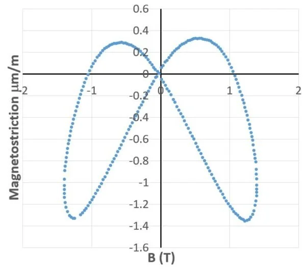
Figure 4 : Magnetostriction as a function of flux density
Magnetostriction Forces in a Grain-Oriented Laminated Core
Another complication is that the transformer industry uses grain-oriented electrical steel. This means that the material’s magnetic properties are anisotropic. It also means that the magnetostriction properties are highly anisotropic. Measurements, in this case, would be even more difficult. In general, material property measurements for grain-oriented steel are available in two directions. The significant anisotropy, shown in the graph in Figure 5, displays the peak-to-peak changes in the strain as a function of flux density. As shown, the strain along the transverse direction (orange) is much higher when compared to the one in the rolling direction (blue).
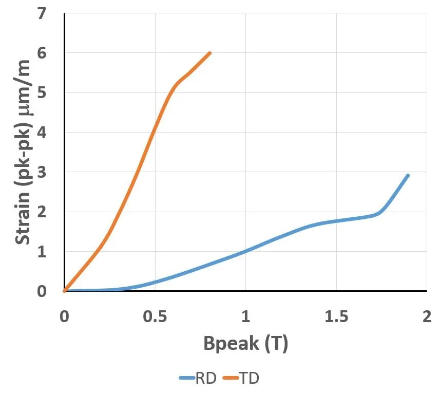
Figure 5 : Peak-to-peak values of strain as a function of peak flux density
Above all, what the designer needs is the evaluation of the noise from the magnetostrictive effect. For such an evaluation, the vibro-acoustic analysis software first requires the magnetostriction forces from an electromagnetic simulation.
For example, the core shown in Figure 6 is a stack of grain-oriented electrical steel laminations aligning the flux path along the rolling directions of the different segments.
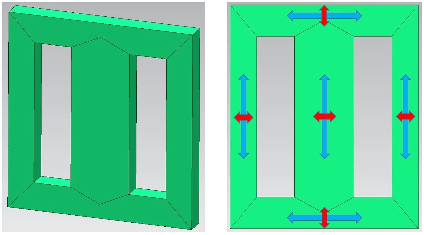
Figure 6 : Laminated core modeled in Simcenter MAGNET, rolling direction (blue), transverse direction (red)
Power transformer development is a multi-objective (cost, time, quality) process that equipment manufacturers must get right the first time. This is because, in the energy and utility industries, the physical prototype is the product. In these industries, physical iterations are really expensive. Manufacturers must therefore understand the transformer behavior as quickly as possible. The new release of Simcenter 3D 2212 provides this physics-based insight into transformer behavior. That is EMAG, structural, and acoustics engineering challenges in one CAD-centric multi-physics platform with traceable workflows. That is, the different physics attributes (EMAG, structural, and NVH) are verified ensuring overall product performance. This avoids over-engineering based on a single physics. Maintaining geometric links to a reference primary CAD model propagates geometric changes automatically, keeping the simulation (CAE) results up to date and ensuring their relevance in product development decisions. Traceability standardizes processes, speeding up workflows by reducing the chances of duplicating tasks unnecessarily, and enhancing collaboration across multiple teams.
Credit: Siemens Digital Industries Software